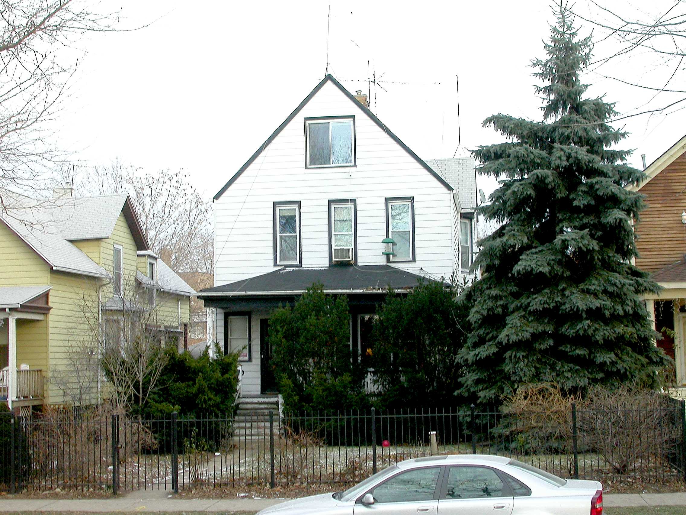
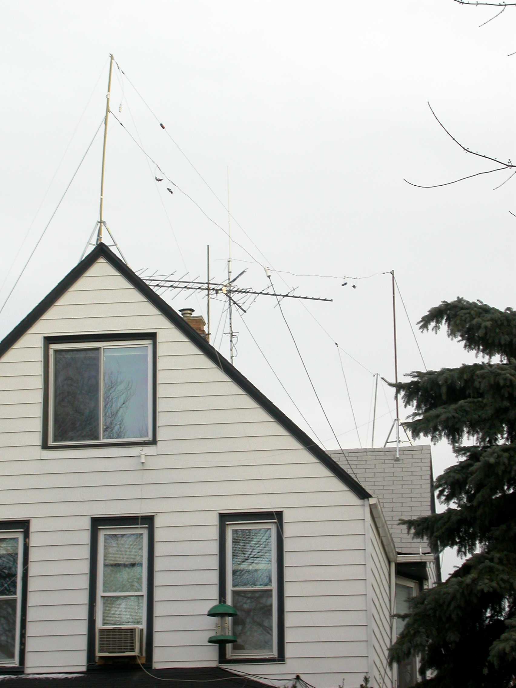
This is K9YC's former QTH, a 110-year old, wood frame 2-flat house in a Chicago residential neighborhood about 2 miles west of Lake Michigan and 6 miles north of the Loop. The ham shack was just inside the window by the bird feeder. The house was sold and all of these antennas are now in California. Some are in the air, and some are still on the ground. The new antenna farm is in the planning stage, with temporary antennas in place.
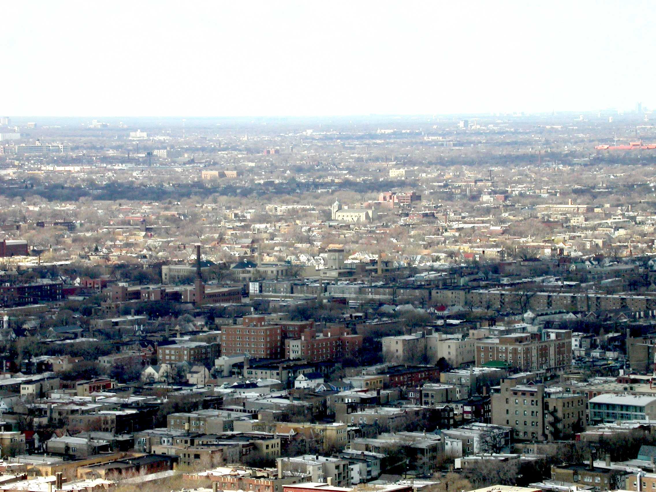
The photo below was taken from the roof of a 600-ft tall building on Lake Shore Drive that is home to the NS9RC 442.075 MHz repeater. K9YC was nearly at the center of the photo, midway between the tall smokestack and the small house with the dark red roof. An electric-powered commuter train line is just across the street, and the train stop is one block south. The complex of red brick buildings houses a small hospital and retirement home. The building with the smokestack is the corporate headquarters for Newark Electronics. Wrigley Field is about 2 miles SSE.
K9YC's Chicago Antenna Farm might better have been described as a weed patch, with wires running every which way, supported by low cost TV antenna masts and guy wire. In fact, my major reason for putting up this web page was to show that you don't have to have perfect (or even very good) antennas to have a good time in ham radio. I've been a ham for 51 years, and until I moved to Santa Cruz this spring, this modest collection of wires was the best antenna farm I'd ever had! Like many hams, I've gone through several long periods of inactivity, concentrating on raising a family and running my own small business. I visited the Field Day site of a local ham club in the summer of 2003, sat down at the CW station, and got up 6 hours later.
The next month I pulled the Omni A out of the basement and started putting up antennas, Over the winter, I upgraded the shack to include an Omni V.9, TS850, K2/100, IC-746, and K2/100. During the summer of 2004, I added a Titan amp (the original). In about 27 months of activity from this QTH, I worked 181 countries, including 126 on 40 meters, 78 on 80 meters, and 20 on 160 meters. In that same time frame, I worked all states on 80 and 40, and all but AK and HI on 160! Nearly all of this was with 100 watts. I worked 236 grids and 44 states on 6 meters. In fact, my biggest problem in working DX was hearing them -- I have a lot of noise from all of the electronic devices in my home and those of my neighbors, all of which adds to the general noise floor produced by a city of 5 Million people.
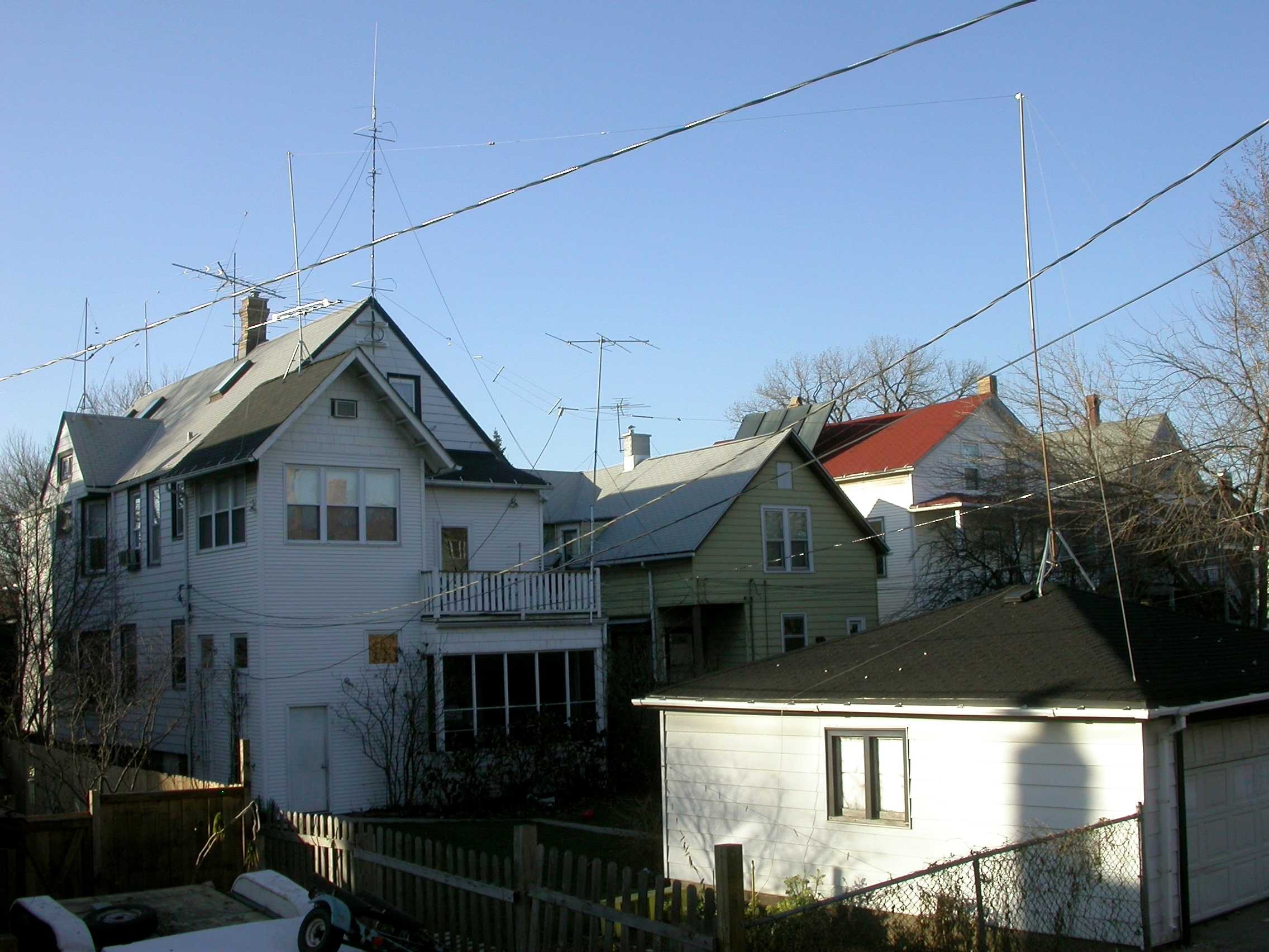
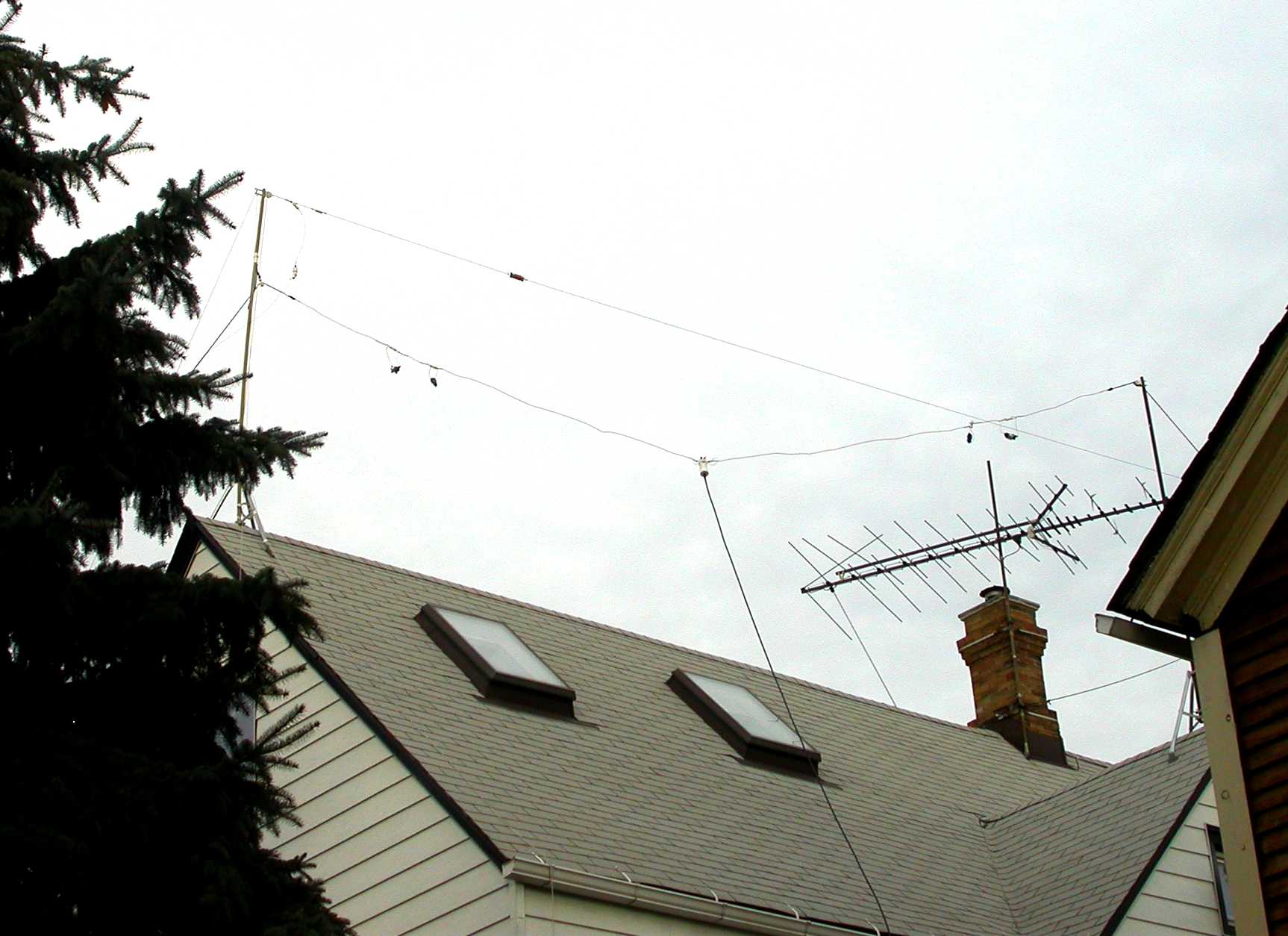
The 80/40 Trap Dipole The mast on the garage roof supported one end of the 80/40 meter dipole; the other end was supported by another mast at the front of the house (photo below). The feedline for this antenna is barely visible alongside the house. It was some old (discontinued) Belden 75 ohm KW twinlead -- very low loss on 160-30 meters, but losses increase above that range. This antenna was roughly 45 ft high at the front of the house, sloping down to about 40 ft where it tied to the garage. The traps were loading coils that resonate with their own capacitance, and were built by Barry, KU3X, operating as HyPower Antenna Company. Their design allowed the antenna to fit between the antenna supports that could put up on my city lot. I also used this antenna on 30 meters -- it worked pretty well into Europe, but was poor going West. It's now hanging between two beautiful Madrone trees in Santa Cruz.
Trap Dipole for 20, 15, and 10 Meters: The other half of the 80/40 dipole was supported by a TV mast at the front of the house. The mast also supported one end of a trap dipole for 20, 15, and 10 meters using Unadilla traps. This antenna was more or less broadside to Europe, and was about 40 ft high.
Three-Wire Dipole for 20, 15, and 10 Meters: This very nice dipole for 20, 15, and 10 is barely visible in the photo of the back of the house. It ran from the base of the mast at the back of the house to the middle of the mast on the garage. This "cloud-warmer" was a bit low for DX, but it made a lot of noise on the East Coast in domestic contests. It was also a bit more efficient than the trap antenna. That's a DX Engineering balun at the center, The spacers are made from 1/2" UV-resistant PVC conduit. It's now up in the air in Santa Cruz.
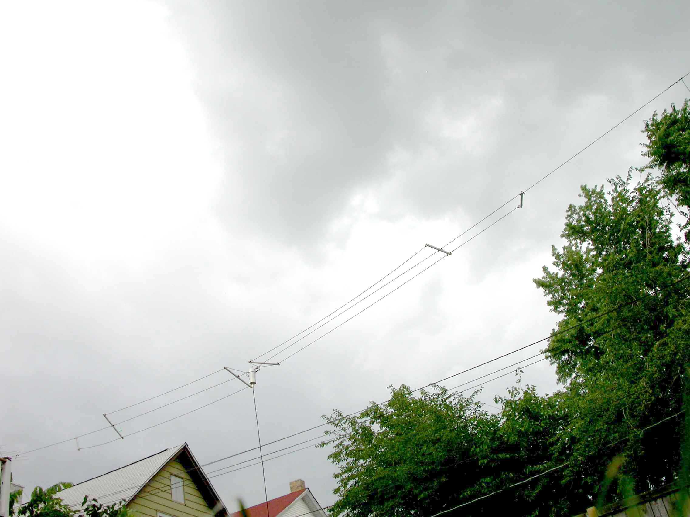
A top-loaded vertical for 80 and 160:. The 80/40 dipole ran East-West (that is, it was broadside North and South). To work East and West, on 80, and to work 160 meters, I tied both sides of the feedline together and loaded it against "ground" (or, more properly, a counterpoise) that consisted of a half dozen driven rods, a dozen or so short radials (30 ft typical), and 135 linear feet of a 5 ft high wrought iron fence that ran around the front of the lot. This antenna worked quite well on 80 meters, and was roughly 10 dB better than the dipole going west (which was off the end of the dipole). The counterpoise was a VERY important part of this antenna, because it lowered the resistive component of the return path for antenna current. This lower impedance increased antenna current and increased the efficiency .
Two Improvised Antennas are barely visible at the front of house. The DX Engineering balun for a 30 meter dipole made from #22 wire was hanging just below the large window on the third floor. The south leg ran over to a large fir tree, the northwest leg sloped down and was tied off to a fence. The other antenna was a quasi-vertical, improvised from one of the guy wires (#12 copper) running from the porch roof to the top of the mast that held up the 80/40 dipole and the 3-band 20/15/10 trap antenna. There were about a dozen radials, varying in length from about 15 ft to about 32 ft. This vertical was pretty good on 30 meters (especially to the west) and on 10 meters. The ham shack was just inside the window by the bird feeder.
Some observations about TVI and RFI. The photos clearly show that these antennas were quite close to the TV antenna (on the chimney) and an FM receiving antenna (on a mast near the rear of the house) pointed at a suburban public station that plays great jazz (WDCB). All of these antennas were also within 20 ft of all my home audio gear. The house is 60 ft deep by 25 ft wide, and sits on a 45 ft-wide lot. My neighbors' houses were 15 feet from mine on either side. I never had a complaint from neighbors. I had no TVI or RFI at home with 100 watts (except on 6 meters), but adding the Titan amp on HF changed that. I then added a high pass filter to the TV antenna and a bandpass filter to the FM antenna. The XYL can now enjoy both FM and TV while I'm pounding brass at full power.
VHF and UHF Barely visible on the mast at the rear of the house (top photo) were stacked 6m and 2m PAR loops and a Diamond X200 vertical. The 3-element Yagi strapped to the deck was for 6 meters, and had an Armstrong rotor. I was looking for a place to put it when I decided to move. The loops were at about 50 ft, the Yagi at 25 ft, the Diamond at 55 ft.
As part of my business, Audio Systems Group, Inc., K9YC is involved in an ongoing program of research to advance the state of our art, and publishes the result of that work so that others can learn from it. Most of the research is published in the form of technical papers presented to the Audio Engineering Society. Our research is self-supported, and authors of technical papers are not compensated by the AES.
Understanding How Ferrites Can Prevent and Eliminate RF Interference to Audio Systems This applications note documents research that was subsequently turned into an AES Paper and presented at the October 2005 convention.
Understanding and Eliminating RF Interference This is a handout for a presentation to the North Shore Radio Club on RFI and ferrites.
Understanding and Eliminating RF Interference This is a Power Point presentation for a tutorial on RFI and ferrites for the Northern California Contest Club.
Pin 1 Revisited Neil Muncy called our attention to the Pin 1 problem (the improper termination of the shield of audio wiring to the circuit board rather than to the shielding enclosure) in his classic 1994 paper, reprinted in the June 1995 Journal of the AES. When he wrote his paper, most commercially available audio gear had pin 1 problems. It was, indeed, difficult to find equipment without it -- even the most prestigeous consoles had serious pin 1 problems! Over the next decade, the better manufacturers redesigned their products to correct their mistake, but sadly, many have not done so. This is the first installment of a two-part article published in the SynAudCon Newsletter.
Pin 1 Revisited -- Part 2 This is the second installment of a two-part article published in the SynAudCon Newsletter.
All of our publications can be accessed through our main website, ASG Publications
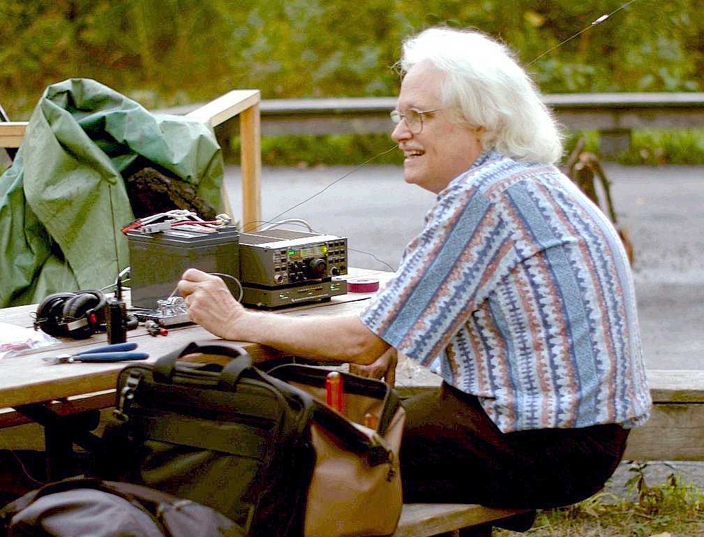
K9YC working 30 meters at the North Shore Radio Club's annual QRP night. -- Photo by KC9GLI